
ZL vertical self-priming pump working principle and composition
1.1 Working principle
Before the vertical self-priming pump is working, the pump body and the inlet pipe must be filled with water to form a vacuum state. When the impeller rotates quickly, the blades will cause the water speed to rotate, and the rotating water will fly out of the impeller under the action of centrifugal force. After the water inside is discharged, the central part of the impeller forms a vacuum zone, and the water is pressed into the inlet pipe through the pipe network under the action of atmospheric pressure (or water pressure), so that the cycle is endless and continuous pumping is realized.
1.2 Components
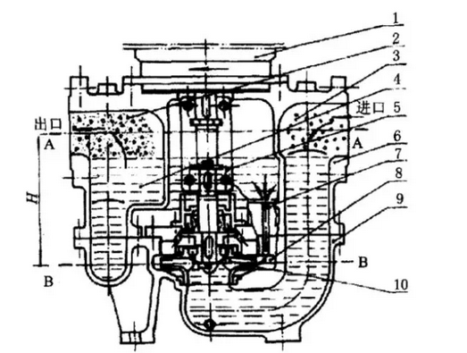
The basic structure of a vertical self-priming pump consists of an impeller, a pump body, a pump shaft, a bearing, and a seal ring. The impeller is the core part of the self-priming pump. It has high rotation speed and large output. The pump body is also called the pump casing. It is the main body of the pump and plays a supporting and fixing role. The role of the pump shaft is to connect the coupling and the motor, and the The torque of the motor is transmitted to the impeller; the bearing is a component that is sleeved on the pump shaft to support the pump shaft, and there are two kinds of rolling bearings and sliding bearings; the seal ring is also called a leakage reduction ring, and the internal leakage is reduced to increase the return resistance, and the impeller and the pump housing are delayed. The service life is provided with a seal ring at the inner edge of the pump housing and at the impeller foreign aid joint.
2. ZL vertical self-priming pump disassembly
2.1 Basic requirements for disassembly
(1) Understand the structure of the pump and be familiar with the working principle;
(2) When the parts have requirements for the assembly position and angle, mark them before disassembling so that they can be smoothly assembled in the future;
(3) The order of disassembly is reasonable;
(4) When disassembling, suitable tools should be used. It is forbidden to scoop, knock, and fight uncivilized construction activities.
2.2 Preparation before disassembly
(1) Master the operation of the pump and prepare necessary drawings and information;
(2) Prepare maintenance tools, measuring tools, cranes, accessories and materials, and wear labor insurance products;
(3) Cut off the connection between the power supply and the equipment and the system, and hang up a warning sign “Man inspects, prohibits closing†on the inspection pump power control box, and put the medium in the pump to meet the equipment safety and inspection conditions;
(4) The maintenance personnel will shut off the front and rear gate valves of the self-priming pump and check if there is pressure in the pump outlet pressure gauge.
2.3 Removal Method and Sequence
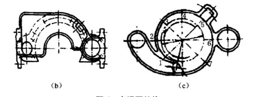
In order to improve efficiency, reduce repair time, and ensure the quality of inspections, attention must be paid to the order and method of dismantling. General centrifugal pump disassembly sequence is to first dismantle the pump's auxiliary equipment, after the disassembly of the pump body parts; first remove the outside, then remove the interior. Self-priming pump structure shown in Figure 1.
3. Overhaul of major components
3.1 bearing maintenance
If the pump is running with vibration, dismantle the bearings first to inspect for bearing wear and changes in geometry. Should generally check the following:
(1) The roundness of the bearing shall not be greater than one thousandth of the shaft diameter, and the exceeding of the standard shall be replaced;
(2) The shaft surface roughness should meet the requirements;
(3) The contact area between the shaft diameter and the bearing shall be 60% to 90%, and there shall be no radial or axial scratches on the surface.
(4) The inner and outer rings of bearings should not be derailed and should be flexible;
(5) The housing and bearing should be in close contact.
3.2 Overhaul of mechanical seal
(1) First use a special tool to properly remove the mechanical seal and static ring, and check the wear condition of the end face. All the rotors installed in the pump should be tested for dynamic or static balance regardless of the power.
(2) In order to ensure that the sealing surface does not leak, the dynamic and static surfaces can be pressed on the fitter's platform and pour on water to make a leakage test. If the static water does not leak, the surface roughness and flatness of the sealing surface meet the requirements. The deviation of the squareness of the end face during installation is not more than 0.015mm.
4 Assembly of main parts
The assembly sequence of the self-priming pump is the reverse of the disassembly sequence. Note the following points during assembly:
(1) Clean all components before assembly, and lubricate the mating surfaces of each component when assembling;
(2) When assembling the components, they must be positioned and reinstalled according to the marks marked on disassembly;
(3) Pay attention to the sequence when tightening the bolts. They should be symmetrical and tightened. Generally, they must be tightened several times in order to ensure that the connecting bolts are tight and even.
4.1 Self-priming pump assembly of rolling bearings
(1) After the data of each department has been checked and qualified before assembly, lubricate the journals and put the cleaned bearings on the journals smoothly and vertically;
(2) Then use a copper rod to gently tap the bearing inner ring face symmetrically, so that the bearing is in place.
4.2 Mechanical Sealing
(1) After the relative position of the rotor and the pump body is fixed, the mounting position of the mechanical seal is determined. According to the installation size of the seal and the position of the stationary ring in the gland, the positioning dimension sealed on the shaft or the shaft sleeve is calculated;
(2) Install a mechanical moving ring. After the ring is installed, it must be ensured that it can move flexibly on the shaft;
(3) Assemble the assembled static ring part and moving ring part;
(4) Install the seal end cap in the seal body and tighten the screw.
5 matters needing attention
(1) Open the gate valve. Note that when it is open to the maximum, it will retreat two or three times to prevent it from opening after being rusted;
(2) No water leakage at the water inlet;
(3) Be sure to add lubricating oil when sealing;
(4) Pay attention to the direction of the machine seal installation;
(5) The direction of rotation must be correct;
(6) The positioning pin above the pump spindle should be installed in place;
(7) Maintenance personnel should wear good labor and defense supplies, and cooperate with more than one person and hang warning signs.
(8) The end of maintenance must be preceded by water and sufficient water.
6. Common faults and handling
Failures may occur during the operation of the pump, but the occurrence and development of a failure is often the result of a combination of factors. Therefore, in analyzing and judging certain failures, it is not possible to discuss the matter in isolation and in a static manner. Instead, it should be comprehensively and comprehensively analyzed to find out the cause of the failure before it can be timely and accurately eliminated.
(1) Causes and Treatments of Pressure Gauges:
1) Check the three-way valve below the pressure gauge, if the switch is drained, there is flow, indicating that the watch is bad, stopwatch change (public number: pump manager);
2) No flow, pressure gauge without pressure, check whether the motor rotation, such as the motor does not rotate, check the circuit;
3) No flow, pressure gauge without pressure, check the coupling is normal;
4) No flow, no pressure on the pressure gauge, check if the coupling key is worn, replace the key;
5) No flow, pressure gauge without pressure, motor speed is not enough, motor is bad or lack of phase, check motor power is normal;
6) No flow, no pressure gauge, air inlet is not completely sealed, check the seal;
7) No flow, no pressure gauge, impeller blocked by garbage, remove the pump and clean up debris;
8) No flow, pressure gauge without pressure, inlet and outlet gate valves closed, gate valve open;
9) No flow, no pressure gauge, no water suction, add water;
10) No flow, pressure gauge without pressure, impeller nut off, impeller off, impeller mounted.
(2) Water Pump Failure Causes and Treatments:
1) If the pump casing is not filled with enough liquid or there is insufficient liquid, additional liquid should be added;
2) Leakage in the suction line, check and eliminate leakage;
3) Excessive leakage of mechanical seals, repair or replacement of mechanical seals;
4) The suction line gas cannot be discharged from the outlet and the gas should be exhausted.
(3) Reasons and treatment methods of loud noise and vibration
1) The foot is unstable and should be reinforced;
2) The pump shaft is bent, the pump shaft is replaced or corrected;
3) There are cavitation phenomena and conditions should be adjusted;
4) Bearing wear is severe and bearings should be replaced;
5) There are impurities in the import pipeline and debris should be removed.
(4) Insufficient water discharge failure causes and treatment methods:
1) The flow rate of the impeller and the suction pipe are blocked and the blockage is eliminated;
2) The impeller or impeller seal wears out and replace the mechanical seal.
(5) The bearing temperature is too high and the cause of the malfunction is as follows:
1) The balance of the rotating part is destroyed and removed;
2) Lubricating oil is too little or deteriorated, and the lubricant is added or replaced as required;
3) The bearing is damaged or loose and should be repaired, replaced or tightened.
7. Conclusion
ZL series of vertical self-priming pump, because of its good self-priming performance, high efficiency, energy saving, stable operation, a drainage, lifelong self-priming, and thus get a lot of promotion. Here, the author records the inspection process of the pump and the handling of common faults to facilitate the understanding and maintenance of the vertical self-priming pump.
SUN YAT INDUSTRY LIMITED , https://www.ernte-eu.com