
1. Can be used in processing equipment, pallet changers and other storage devices;
2. The mechanical structure is reasonable, the material performance is stable, there is sufficient rigidity, it can be deformed under the action of large cutting force, the deformation amount is small, and the service life is long;
3. The workpiece is easy to clamp on the tray, the speed is fast, the precision is high, and it is automatically performed;
4. No manual intervention is required in the processing cycle;
5. It can work reliably under the harsh environment of processing (such as cutting heat, moisture, vibration, high pressure cutting fluid, etc.);
6. Positioning, clamping and chip removal, etc., does not affect the accuracy of the workpiece and the surface quality of the finished workpiece;
7. Easy to control and manage, to ensure that there is no confusion and no errors in the installation of workpieces, transportation and processing.
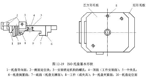
In order to ensure that the pallets can be shared between processing equipment and storage equipment produced by different manufacturers, the International Organization for Standardization has established a pallet standard (ISO/DIS8526-1) with a nominal size of less than or equal to 800mm and a pallet standard with a nominal size of more than 800mm (ISO). /DIS8526-2), specifies the size of the top structure of the pallet directly related to the installation of the workpiece and the size of the underlying structure associated with automated storage. The nominal size of the pallet refers to the width of the top surface of the pallet on which the workpiece is mounted. The size series is 320, 400, 500, 630, 800, 1 000, 1 250 and 1 600 mm. The code of the pallet is composed of the following parts in sequence: 1ISO number; 2 width × length; 3 top surface form number; 4 slot pitch or hole pitch; 5 workpiece positioning mode; 6 pallet positioning mode. Such as ISO85-2-1 000×1 250-1-100-ab, which is a rectangular tray of ISO8526-2, the top surface is 1 000×1 250, with the top surface of the screw hole system, the center distance of the screw hole is 100. The workpiece is positioned by the side positioning block, and the tray is positioned by two tapered holes and two tapered pins on the support. The basic shape of the ISO tray is shown in Figure 12-19.
(4) Combination fixture.
The combined fixture is a combination of fully standardized components. It can be used to build different fixtures and connections according to the processing requirements of the workpiece. There are 8 types of basic components of the combined fixture, namely the base member, the support member, the positioning member, the guide member, the pressing member, the fastener, the fitting and the other member. The combination fixture is characterized by flexibility and versatility; it can greatly shorten the production preparation cycle; components can be reused, manufacturing and management are convenient, long-term economy is good; and computer-aided process design is easy to implement. There are two basic types of combination clips currently in use, namely a trough combination jig and a hole system combination jig. The grooved combination clamp elements are positioned by keys and slots, and the hole combination clamps are positioned by holes and pins. Because the hole combination fixture has high precision, good rigidity and easy assembly compared with the groove combination fixture, it can conveniently provide the NC programming origin (origin of the workpiece coordinate system), which is widely used in FMS.
4. Processing system monitoring
The working process of the FMS processing system is carried out at high speed in an unmanned and unattended environment. To ensure the normal operation of the system, prevent accidents and ensure product quality, the system working status must be monitored. The monitoring contents of the general processing system are shown in Table 12-2.
Table 12-2 Monitoring contents of the processing system 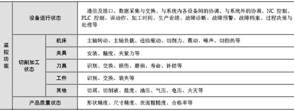
| Previous page | 1 | 2 | 3 | 4 | 5 | 6 | 7 | Next page |
Forklift Alignment Laser Module
In the field of forklift positioning, the laser helps guide the forklift operator place forklifts more accurately.
The top laser aligns fork tines with pallet fork slots to prevent damage to goods. The bottom laser aligns forklift with pallet rack beam to avoid damage to the rack.
Forklift Alignment Laser Module,Green Laser Module,Laser Module,Forklift Laser Safety Warning Light
Changshu Desheng Optics Electronics Co.,Ltd , https://www.ray-lasertech.com