
1 Introduction
In view of the fact that solar photovoltaic modules generate electricity in direct relation with the sunshine intensity and time, as well as the placement and tilt angle of the panels, the current status of most of the brackets can not be adjusted and the power generation efficiency is relatively low, a kind of latitude can be designed according to different latitudes. Regional and adjustable PV system brackets. In this paper, the connection, material, type selection and load analysis of the photovoltaic module support system are analyzed and elaborated in detail. At the same time, the photovoltaic module can not only adjust the horizontal angle according to need, but also has high strength, and can be used in windy and snowy areas. Use, with a certain promotional significance and application prospects.
At present, under the circumstances of global energy supply shortages and increasingly serious environmental problems, the sustainable development of the economy and society has been challenged enormously. The development and use of clean and safe renewable energy resources has received extensive attention. Although there are many kinds of renewable alternative energy sources that have been used so far, the total amount of available water, wind, and tidal energy is too small to meet human needs.
As a renewable energy source with abundant resources, extensive distribution and permanent use, solar energy has great potential for development and utilization. Especially in the 21st century, the solar photovoltaic power generation industry has developed very rapidly. In the near future, solar photovoltaic power generation will not only replace part of conventional energy sources, but will also become the main body of energy supply in the world, and will bring about revolutionary changes in energy development. According to the prediction of the Joint Research Center of the European Union (JRC), by the end of the 21st century, renewable energy will account for more than 80% of the energy structure, of which solar power accounts for more than 60%, fully demonstrating its important strategic position.
The solar photovoltaic module bracket is an important component of the fixed solar panel. Under the premise of obtaining the maximum power generation efficiency of the solar panel, ensuring the safety and reliability of the bracket is a need for consideration and research of photovoltaic module manufacturers. According to the needs of different forms of solar photovoltaic power generation, the bracket system is generally divided into single-column solar brackets, dual-column solar brackets, matrix solar brackets, roof solar brackets, wall solar brackets, and tracking system series brackets. The installation method is divided into floor installation system, roof installation system and building energy-saving integrated bracket installation system.
2. PV module bracket design
2.1 PV module bracket structure
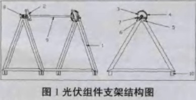
At present, most commercially available solar photovoltaic module mounting brackets cannot adjust the angle. Using the tracking method for solar power generation also wastes a lot of manpower and material resources, and the input-output ratio is limited to a certain extent. This paper has designed a photovoltaic system bracket that can adjust the angle according to different latitude regions (as shown in Figure 1). The bracket system can adjust the horizontal angle according to the needs, not only adapting to the use of ground-based photovoltaic power plants, but also can be used in rooftop photovoltaics. The use of the power station can quickly adjust the mounting angle of the bracket during the installation process, which avoids the shortcomings of the conventional photovoltaic module bracket that cannot quickly adjust the installation angle. At the same time, the component bracket adopts a high-carbon steel structure and the surface is hot-dip galvanized material and has a low cost. With high strength and strong material resistance, it can be used in areas with poor environment. This system includes a triangular main bracket 1, a support connection mechanism 2, a scale positioning plate 3, a positioning hole 4, a plunger type scale pin 5, a pallet 6, a pressure plate 7, a bearing sleeve 8, a connecting rod 9, and a foot support 10. The main bracket of the system is a triangular welding structure. The structure is simple and can withstand sufficient loads. The battery assembly is fixed to the supporting connection mechanism by bolts, and the dial is used to adjust the angle. The scale positioning plate is fixed by the plunger type scale pin, and the supporting plate, the pressure plate and the bearing sleeve are used together with the scale positioning plate, and the connecting rod and the ground leg support are used to increase the strength of the photovoltaic component bracket.
2.2. PV module bracket connection
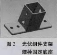
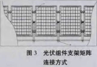
When the PV module system is installed, the base is fixed by embedded bolts, as shown in FIG. 2 . The foot support at the bottom of the bracket is put into the base and connected with the base through the bolt, and then the battery assembly is installed. The photovoltaic module is connected with the support mechanism 2 through the bolt, and the required angle is adjusted by the scale positioning plate 3 and the positioning pin 5, and the installation is completed. A group. In the matrix solar power generation connection, two sets of adjacent component brackets are fixed by fastening tabs 11 to increase their strength, as shown in FIG. 3 .
2.3 PV module bracket material selection
At present, China's commonly used solar photovoltaic stent system from the material points, there are three kinds of concrete stents, steel stents and aluminum alloy stents. The concrete support is mainly used in large-scale photovoltaic power plants. Because it is self-contained, it can only be placed in the wild and has a good foundation, but it has high stability and can support huge-sized panels. Aluminium alloy brackets are generally used in solar applications on the roofs of civil buildings. Aluminum alloys are characterized by corrosion resistance, light weight, and durability, but their low bearing capacity cannot be applied to solar power plant projects.
The steel bracket designed in this paper has stable performance, mature manufacturing process, high bearing capacity, easy installation, excellent anti-corrosion performance, beautiful appearance, unique connection design, convenient and quick installation, and simple installation tools. Steel and stainless steel with structural anti-corrosion materials Parts have a service life of more than 20 years.
2.4 PV Module Bracket Load Analysis
The strength of the bracket mainly includes the calculation of the fixed load (weight and other components itself), wind load and snow load. The wind load refers to the wind pressure from the front of the bracket (downwind) and the wind pressure from the back of the bracket (wind). The bending strength and bending amount of the material, the buckling (compression) of the support arm, and the tensile strength and structural changes caused by normal ground, roof vibration, and settlement.
2.4.1 snow load analysis
Snow load load is shown in Equation 2-1:
S=Cs*P*Zs*As(2-1)
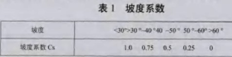
Among them, S is the snow load, Cs is the slope coefficient, and P is the average unit mass of snow (equivalent to snow mass of 1cm, mass of 1m2). The general area is 19.6N or more, and the snowy area is 29.4N or more. Zs is the vertical snow depth (cm) on the ground, and As is the snow area. The amount of snow for the design of the solar cell array surface is set to the deepest snow amount (Zs) on the ground. However, if the snow is often removed and the amount of snow is reduced, the Zs value can be reduced depending on the situation. The slope coefficient is shown in Table 1.
2.4.2 Force Analysis of Wind Speed ​​Load
The PV module bracket designed in this paper is used to check whether the strength and deflection meet the requirements under the wind speed of a class of ten (27m/s).
2.4.2.1 Normal stress check
When the PV module support beam is bent in one direction, the normal stress is shown in Equation 2-2:
![]()
Where Mx is the bending moment of the same section beam in the maximum stiffness plane (x axis); Wnx is the net section modulus (bending section modulus) to the x axis; it is the steel strength design value. According to Equation 2-2, the normal stress is given by Equation 2-3:
![]()
After examining the hardware manual table, the design value is [f], σmax<[f] so the strength requirement is met.
2.4.2.2 Checking Deflection
The maximum deflection of the beam span is shown in Equation 2-4:
![]()
In the formula, l0 is the calculation span of ç²±; S is related to the load form and bearing condition, and the simple supported beam with uniform load is S=5/384; E is the elastic modulus; M is the maximum bending moment across the middle; EI is Sectional bending stiffness. The longitudinal calculation is the same as above.
2.4.2.3 Tensile and compressive strength of the rear support arm
2.4.2.3.1 Upwind
The wind load W acts as a tensile load on the support arm and becomes the upper blow load (lift force). The tensile stress is shown in Equation 2-5:
![]()
P in the formula is tensile tension; A is the cross-sectional area of ​​the support arm, check the tensile strength design value of the Q235 steel [f], <[f], so there is no problem.
2.4.2.3.2 Downwind
When the length of the support post is longer than the width of the section, the probability of bending failure is higher than that of compression failure. This is called buckling of the column. The load at this time is called buckling load. Buckling load (Eulerian formula) is shown in Equation 2-6:
![]()
In the formula, the load is buckling; it is the axial section moment of inertia; it is the coefficient determined by the support conditions at both ends, and the hinge hinge of the two ends is 1; it is the material longitudinal elastic coefficient; L is the shaft length. The tensile strength of the front support is supported by the calculation process.
3. Application prospects
At present, the international energy situation is relatively severe. Every country is trying hard to find new energy that can replace conventional fossil energy. In addition, the safety of nuclear power generation raises questions about the impact of wind and water on the geographical and seasonal conditions. However, solar energy is an inexhaustible source of clean energy that attracts attention and uses. With the widespread promotion and application of large-scale ground and rooftop solar photovoltaic systems in the world, solar photovoltaic power generation has become one of the essential power sources for power supply. At the same time, in order to ensure the reliable, safe and stable operation of photovoltaic module systems, it must be required. All components of the solar module have good wind resistance, snow pressure resistance, corrosion resistance and other properties. The solar photovoltaic module bracket installation designed in this paper not only satisfies wind resistance, snow pressure resistance, corrosion resistance, etc., but also can be applied to ground matrix solar energy and roof solar energy systems. This solar photovoltaic module bracket has a good application prospect in the future photovoltaic power generation applications.
According to the shortcomings of the conventional solar photovoltaic module brackets, combined with the characteristics of solar power generation, a new type of solar photovoltaic module bracket was designed. The unique design structure of PV modules enables the module to have an adjustable angle according to different regions, so as to make full use of local solar energy resources and achieve maximum power generation efficiency of solar modules. At the same time, the connection method, material selection and force analysis of the bracket load of the PV module are analyzed and practiced in detail, so that it has good physical properties such as shock resistance, wind resistance, snow pressure resistance and corrosion resistance, so that the photovoltaic module can be used More extensive territory.
Sameless pipe
Seamless pipe as the name suggests is a pipe without a seam or a weld-joint in contrast to Seam or Welded pipe. In a Seam or Welded pipe, the seam or the weld-joint is the weaker part of the pipe limiting the strength of the pipe to the strength of the weld-joint. Whereas the seamless pipe does not have any such joint and thus has uniform structure & strength all over the pipe body.
Some commonly used models are
Api5L Seamless Pipe ,A53 Gr.B Seamless Pipe,Astm A106 Gr.B Seamless and so on.Advantage
The seamless pipe can withstand higher pressure, higher temperature, higher mechanical stress & corrosive atmosphere and find wide applications in Oil & Gas.
Applications
Applications in petrochemical, chemical, chemical, chemical fertilizers, electric power, automobiles, bearings, machinery and structures.


API 5L Seamless Steel Pipe ASTM A106/A53 GR.B seamless steel pipe
Standard of carbon seamless steel pipe

Packaging & Delivery
Packaging Details
Plastic caps on both ends, Steel bundle, Woven bag or acc. to customers' request.
Delivery Time
15 days after receiving deposit
Seamless Steel Pipe
Seamless Steel Pipe,A53 Gr.B Seamless Pipe,Api5L Seamless Pipe,Astm A106 Gr.B Seamless
HEBEI CHENGYUAN PIPE INDUSTRY GROUP CO.,LTD , https://www.hbcytube.com