With the rapid development of the industry, the structure, shape and materials of mechanical products are constantly changing, and the processing precision of products is constantly improving. Machine tools and equipment are required to have high flexibility and versatility to meet the frequent production targets. The need for change. The traditional machining process is to clamp the workpiece on the trampoline, the workpiece does not move, the boring tool is mounted on the boring tool boring bar, the boring tool rotates and the axial feed is processed, but the production efficiency is low and the finished product is high, in order to To solve the above problems, by transforming the CW61125 lathe part, the CW61125 lathe was changed to the special deep lathe lathe, and the machining process was improved, and the trampoline boring was changed to the lathe boring.

1. The basic structure and components of the machine
Add the corresponding parts to the lathe to achieve the purpose of boring, reaming and rolling. During machining, the workpiece is rotated and the tool is fed. When the hole is bored, the cutting fluid enters the inner hole of the mast through the end of the mast (the tail of the drill pipe shaft), reaches the cutting area of ​​the tool, and lubricates and cools the cutting area. The chips are fed into the chip box through the chip hopper at the bed end of the workpiece. When rough, the aperture accuracy is IT8-10, and the surface roughness value Ra is 3.2 to 6.3 μm. In the case of fine boring, the aperture accuracy is IT7-9, and the surface roughness value Ra is 1.6 to 3.2 μm.
The main components of the machine tool are as follows:
(1) The bed part. Borrowing the original CW61125 lathe bed body, the rear end can be connected to the long bed body, the guide surface is medium frequency quenched, and the whole is ground.
(2) The head box part. Borrow the original CW61125 lathe head box, gears, bearings for repair, replacement parts.
(3) Shantou bracket. It adopts two lower half-wafer structures, supports the mast through the support sleeve, and has a button plate and a meter in front of it, which almost contains all the movement control buttons of the machine tool. Therefore, the hammer bracket is also the operation center of the machine tool. The motorized quick device drives the hoe bracket to feed back and forth along the bed. Figure 1 shows the assembly of the boring bar. Two adjustable boring tools are mounted on the arbor. In the figure, the boring tool 4 is used to rough the hole on the workpiece, and the boring tool 5 is used to finely boring the hole on the workpiece to ensure that the workpiece can be coarsely and finely processed in one feeding. During machining, the spindle drives the boring tool to rotate, and the workpiece is fixed in the lateral direction without any change. The lathe pallet moves to the left in the longitudinal direction to complete the roughing and finishing of the workpiece. When finished, retract the knife in the longitudinal direction.

Figure 1 boring bar assembly diagram
(4) The part of the carriage. The mast holder is fixed on the carriage and is coupled to the mast by means of a locking sleeve. When feeding, the feed box transmits power to drive the lead screw, and the lead screw starts to rotate. The rotating screw causes the nut on the bar to move in the axial direction. The axially moving nut drives the carriage to reach the carriage feed. the goal of. When the carriage moves quickly, the fast motor behind the carriage drives the worm wheel to drive the nut to rotate, which drives the carriage to move quickly. When manual, push the push rod in the center of the hand wheel to make two m2×17mm gears mesh, turn the handwheel to drive the worm wheel, and drive the nut to rotate, so that the carriage moves axially. Manual and fast motion are interlocked with microswitches.
(5) The bracket of the boring bar. The bracket of the boring bar is divided into two upper and lower half-watt structures, so that the purpose of the boring bar is to be updated and replaced. The boring bar holder functions to assist the support mast. For the slender mast, the number of brackets needs to be increased appropriately. The movement along the bed rail is driven by the carriage or can be driven by a manual device.
The feeding of the file is realized by a bracket, and a feeding screw is installed in the middle of the bed. The screw is composed of a plurality of sections, the two ends are supported by the bracket, and the front of the bed is provided with a rack, and The gears of the manual unit are meshed for use with the moving center frame and the mast bracket (see Figure 2).
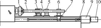
Figure 2 Schematic diagram of the file feeding device
1. boring tool assembly 2. Pipe fittings 3. 绶 oil support frame 4. mast
5. Mast support frame 6. Mast fixed support 7. Silk box
8. Clutch 9. Reducer 10. Motor
(6) Feed system. The feed box is mounted at the end of the bed and the feed screw is mounted in a recess between the rails. Driven by AC servo motor, the lead screw can obtain stepless speed regulation of 0.5~60r/min, and the carriage can get speed of 5~600mm/min.
(7) Center frame and workpiece carrier. Borrow the original lathe center frame and workpiece carrier.
(8) Cutting fluid supply system. The cutting fluid supply system is behind the machine tool. The main components are fuel tank, oil pipeline, storage box and pump station. There are two main functions of the cutting fluid. The first point is the cooling effect, and the second point is to remove the chips to the chip box and the fuel tank. The hydraulic system of the cooling system consists of a motor with a gear pump that provides a flow rate of 300 L/min and has a cooling filter function.
(9) Chip discharge bucket. The special chip bucket is added to automatically discharge the chips and cutting fluid into the chip box to prevent splashing of the cutting fluid.
(10) Control system for the electrical part. There are mainly electrical control systems, electrical control cabinets and drive units.
2. Basic technical parameters of the machine tool
(1) Maximum diameter of the pupil:
500mm; center height (from flat rail to spindle center): same as the original machine tool; maximum machining workpiece length: 4 000mm; main motor power: same as the original lathe; feed motor power: 5kW; machine spindle number, speed: and The original lathe is the same; the carriage motor: 5kW, N=2 880r/min; the feed speed range: 0~600mm/min; the fast moving speed of the carriage: 2.8m/min; the cooling pump motor: 5kW, N=960r/min Cooling system rated pressure: 0.36MPa; cooling system flow: 200L/min.
(2) When rough, the aperture accuracy:
IT8-10, surface roughness value: Ra = 3.2 ~ 6. 3 μ m; precision, aperture accuracy:
IT7-9, surface roughness value: Ra = 1.6 ~ 3.2 μm.
(3) Feeding speed: determined according to the specific conditions of processing, generally 10~60mm/min; cutting speed: generally determined according to the hardness of the material, the structure of the tool design and the material of the workpiece to be processed, generally 60~90m /min. The processing site is shown in Figure 3.
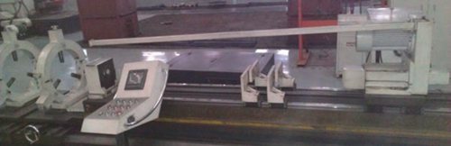
Figure 3 processing site
3. Conclusion
The equipment is simpler and easier to implement after modification. It does not need to spend too much money, and utilizes the original common equipment, so that the original equipment can be reused by tapping potential, which expands the use range of the lathe and improves the utilization rate of the machine tool, thus The production efficiency has been greatly improved, and the mechanical labor intensity of the production workers has been reduced, the production cost has been reduced, and good processing results and good economic benefits have been produced in practical applications.
Modular
houses are created in sections, and then transported to the home site for construction
and installation. Although the sections of the house are prefabricated, the
sections, or modules, are put together at the construction much like a typical
home. Quick installation is the primary advantage of Modular Building as most
of the interior decoration was done in the factory. Zhongda has manufactured
modular houses for the US, Australia, and the UK projects in varies of building
types such as hotels, apartments, and villas etc. 
Modular Building
Modular Building,Modular House,Modular Office Building,Modular Building Construction
Zhongda Steel Structure , https://www.zhongdametal.com
