Our company specializes in the production of centrifugal casting pipes for the petrochemical industry. As our operations continue to grow, we are in urgent need of two deep-hole boring machines. To reduce costs and maximize efficiency, we plan to convert two idle CW6163 lathes into deep-hole boring machines after a complete overhaul. This approach not only meets the increasing demand for production but also significantly cuts down on investment expenses.
**1. Main Design Parameters and Technical Requirements**
(1) **Technical Requirements for Machining the Inner Hole of Centrifugal Casting Pipes**
The inner hole of the centrifugal casting pipe must meet a dimensional tolerance of 0 to -0.8 mm. The pipe length ranges from 3 to 5.5 meters, and the surface roughness should be Ra = 0.8 μm.
(2) **Technical Requirements for the CW6163 Lathe**
- The bed length must be extended to at least 12 meters.
- The lathe must undergo full overhaul to ensure it meets machine overhaul standards.
- The tailstock and turret will be removed, with focus on overhauling the bed surface, guide rails, tail bottom plate, slide plate, and all gear transmission systems.
**2. Working Principle**
The workpiece is clamped using a single-acting chuck on the left end, while the right end is secured and centered by the inner cone of the squeegee support frame. This setup also ensures a tight seal. The rotation speed of the pipe is controlled by the headstock drive system.
The feeding mechanism is achieved through a support frame mounted on the slide box. A feed screw is installed along the middle of the bed, composed of several sections supported by brackets. A rack is located at the front wall of the bed, meshing with the gear of the manual device for the moving center frame, oil support frame, and mast support frame (see Figure 1).
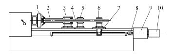
*Figure 1: 1. File assembly 2. Pipe fittings 3. Oil support frame 4. Mast 5. Mast support frame 6. Mast fixed support frame 7. Main box 8. Clutch 9. Reducer 10. Motor*
**(1) Design of the Slinger Support Frame**
The sling support frame is mounted on the original lathe’s base plate and fixed to the bed rail. It can move along the rack to accommodate different pipe lengths, ensuring accurate center height and alignment (see Figure 2).
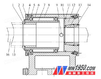
*Figure 2: 1. Cone disk 2. Positioning shaft 3. End cover 4. Felt ring 5. Bearing 6. Spacer 7. Positioning sleeve 8. Pipe support frame 9. Oil hole 10. Packing hole 11. Sealing ring 12. Positioning end cap 13. Locking the positioning sleeve 14. Locking the thread nut 15. Mast 16. Pipe fittings*
**(2) Role of the Slinger Support**
- Injects cutting fluid into the pipe and seals it.
- Supports the mast.
- Positions the hoe head.
- Supports and secures the workpiece.
A cooling pipe connects to the pump on the back of the oil slinger, delivering cutting fluid to the cutting zone via the squeegee support. A guide sleeve inside the cone guides the hoe, and different tools are used for varying diameters, requiring corresponding sleeve replacements. A taper sleeve at the end of the squeegee support frame supports the mast, and adjustment nuts allow for fine-tuning when wear or vibration occurs.
**(3) Mast Support Frame**
Due to the long length of the mast, it may sag under its own weight. The mast support frame prevents bending and reduces stress during the machining process (see Figure 3).
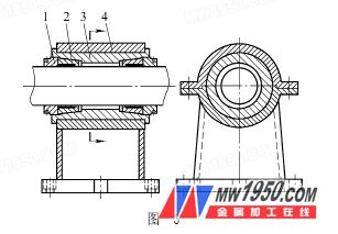
*Figure 3: 1. Locking the thread nut 2. Positioning the locking sleeve 3. Positioning sleeve 4. Mast support frame*
**(4) Mast Fixed Support Frame**
The mast fixed support frame is mounted on the original lathe slide, matching the center height of the oil support frame. It is positioned at the rear of the mast and can move left and right to accommodate different pipe lengths. During feeding, the feed box drives the screw, causing the nut to move axially and driving the bed saddle automatically. A DC motor with a reduction gearbox powers the lead screw, and a safety clutch adjusts engagement force via a spring. In case of overload, the clutch disengages, triggering a micro switch to stop the saddle and display an error signal (see Figure 4).
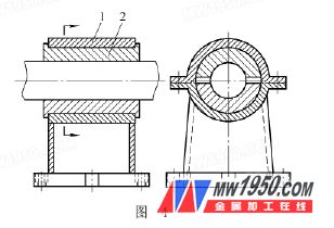
*Figure 4: 1. Mast fixed support frame*
The boring shaft is connected to the shank via a square thread. The new deep-hole boring head features five cutting edges with chip pockets for efficient chip removal, ensuring continuous and fast boring. Five springs are fixed on the guide sleeve, aligning the guide bar and cutting edge within the same cylinder. Cutting fluid is supplied externally and flows forward through the guide bar and cutting edge, providing effective cooling and lubrication for high-speed, precision deep-hole boring (see Figure 5).
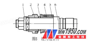
*Figure 5: 1. Flange nut 2. Boring tool 3. Spacer 4. Spring 5. Support guide sleeve 6. Boring shaft*
**3. Cutting Fluid Circulation System**
The primary function of the cutting fluid circulation system is to cool the cutting area and remove chips, directing them to the scraper and fuel tank. In deep-hole boring, the tool works continuously with five teeth, generating significant heat. Since the tool is inside the workpiece and visibility is limited, the system must flush out chips and provide cooling. The flow path is as follows: water tank → water pump → oil support frame → workpiece → steam head → bed head clamping mechanism → water tank → water tank. A high-flow, low-head pump, such as the 2B-31 centrifugal clean water pump with a 4kW motor, is suitable for this application.
Beryllia Ceramic
Beryllium oxide ceramics are ceramics with beryllium oxide as the main component. Mainly used as materials for large-scale integrated circuit substrates, high-power gas laser tubes, heat sink shells of transistors, microwave output windows and neutron moderators. Beryllium oxide ceramics have the characteristics of high thermal conductivity, high melting, strength, high insulation, low dielectric constant, low dielectric loss and good packaging process adaptability. And the field of optoelectronics technology has received attention and applications, especially in high-power semiconductor devices, high-power integrated circuits, high-power microwave vacuum devices and nuclear reactors. It has always been the mainstream ceramic material for the preparation of high thermal conductivity components. It has been used in the military field and the national economy. To a very important role.
Dongguan Haikun New Material Co., Ltd. , https://www.hkceram.com
